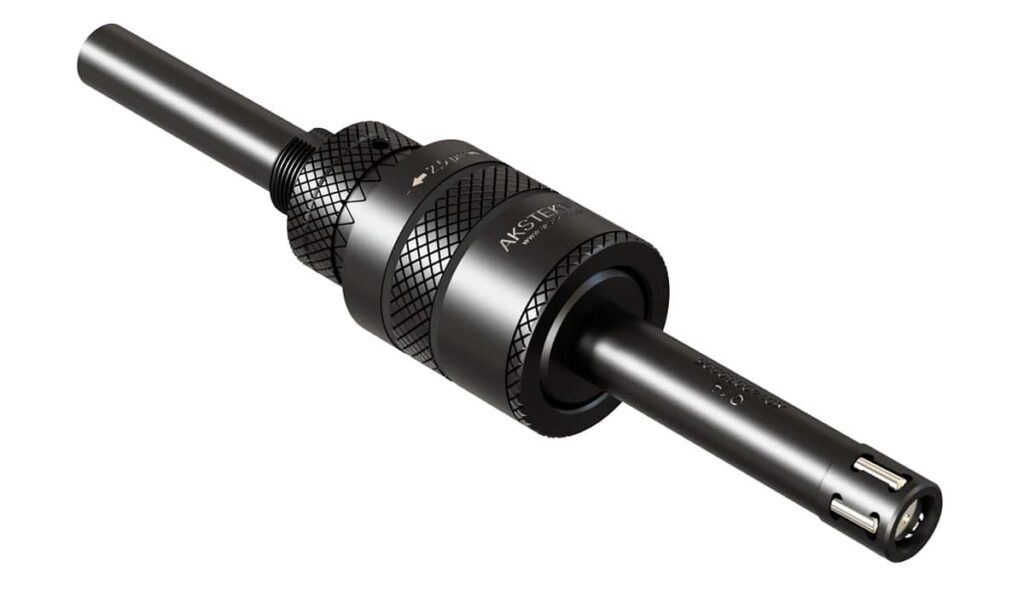
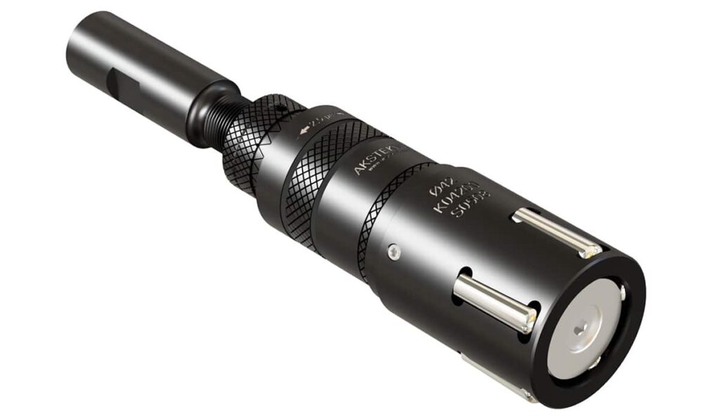
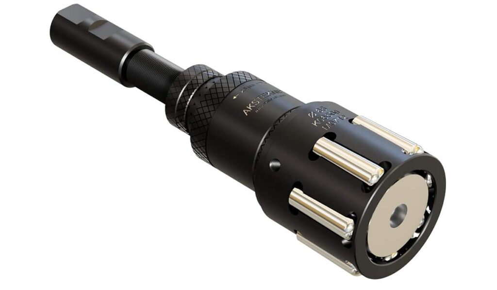
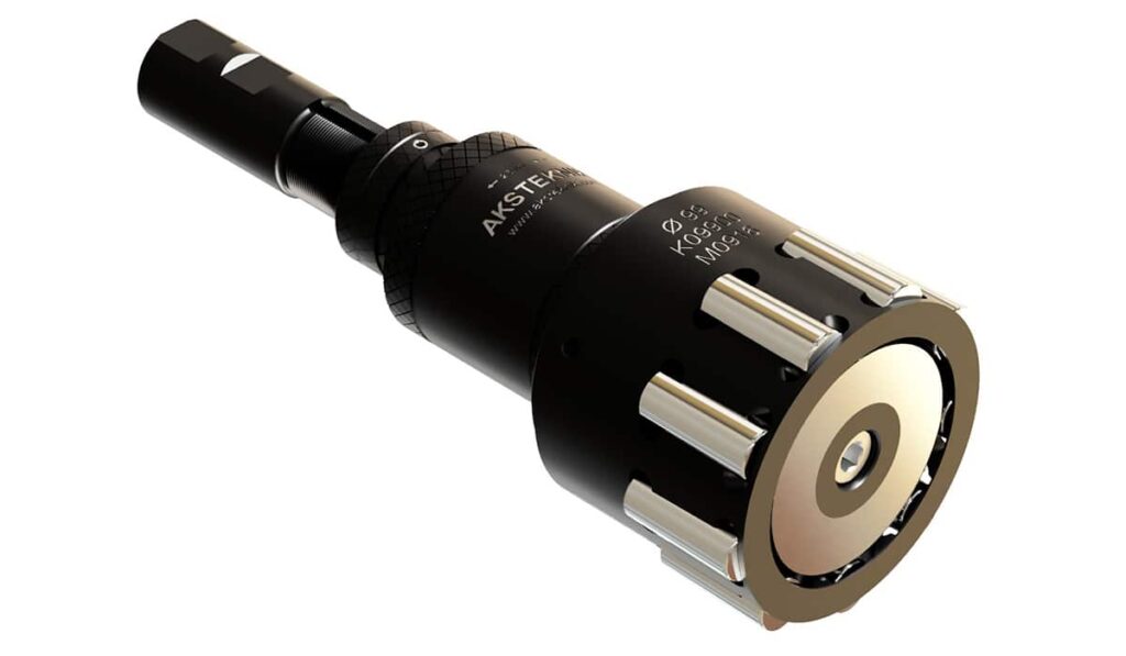
Delik Ezerek Parlatma Takımları
- Home
- Ezerek Parlatma
- Delik Ezerek Parlatma Takımları
OVERVIEW
Delik Ezerek Parlatma Takımları
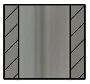
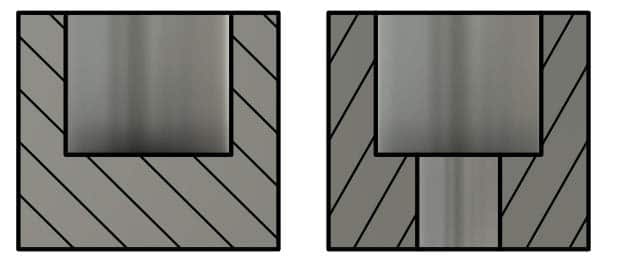
AÇIK DELİK | KÖR DELİK | |
|---|---|---|
|
| |
KENDİ ÇEKER HELİS AÇIK DELİK (S) | MAKİNA BESLEMELİ AÇIK DELİK(M) | MAKİNA BESLEMELİ KÖR (B) |
| 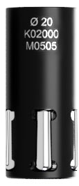 | 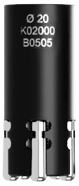 |
MANUEL MAKİNALAR ,ÜNİVERSAL TORNALARDA VE SÜTUNLU MATKAPLARDA KOLAY KULLANIM | CNC TEZGAHLAR İÇİN İDEAL | TÜM MAKİNA MODELLERİ İÇİN MAKİNA BESLEMELİ |
Ezerek Parlatma Nedir?
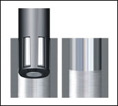 |
| Delik İçi Ezerek Parlatma İşlemi |
Adından da anlaşılacağı gibi bilyeler yardımıyla yüzeydeki pürüzlerin ezilmesidir. Bu ezme sonucunda ayna gibi yüzeyler elde edersiniz. Genel olarak deliklerde ve mil üzerlerinde uygulanır. Isıl işlem olmadığı takdirde hertürlü metalde çok başarılı sonuçlar verir. (alüminyum, döküm, çelik, paslanmaz çelik, bronz gibi tüm metaller uygundur) Torna ve rayba gibi önişlemden sonra uygulanır. Soğuk çekme dövme gibi işlemlerden sonra uygulanabilmesi için talaş kaldırılması gerekir. Yani yüzeyde talaş kaldırmada oluşacak pürüz olmalı ki ezilsin. Delik içi takımlarda 2.5 mikron yani 0.0025mm hassasiyetle çap ayarı yapabilirsiniz.
En önemlisi işlem süresi bir kaç saniye gibi çok kısadır.
Ezerek parlatma önişlemden (tornalama,raybalama vs) geçmiş parçaları pürüzsüz hale getirirken aynı zamanda ölçüye getirir. Hassas yüzeylerin istendiği üretimlerde honlama, lepleme, taşlamanın yerine saniyeler içinde mükemmel bir yüzey elde edilir.
Çalışma Presibi:
Ezerek parlatmanın temeli belirli bir yolu takip eden bilyenin, kendisine uygulanan kuvveti metal yüzeye aktarmasıdır.
Şekil’de ezme işlemi gösterilmiştir. Ön işlemi yapılmış olan (torna, rayba vs.) metal yüzeyine hassas bir mekanizma yardımı ile, bilyelerin teması ile gerçekleşir
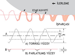 |  |
| Ezme İşlemi | Yüzey Pürüzlülüğü |
Metallerin mikro yüzey profiline bakıldığında tepe ve çukur diyebileceğimiz pürüzleri görürüz. Ezme işlemi sırasında tepelerin üzerine kuvvet uygulanmakta çukurların dışarı çıkması sağlanmaktadır . Bilyenin işparçasına teması ile metalin akma noktası geçilir ve plastik deformasyon meydana gelir. Bu bölgede metal milimetrenin yüzdelikli hanelerinde ezilmektedir. Plastik deformasyonun ardından malzeme bir miktar elastik olarak toparlanır. Burada bilye metale son kez temas ederek, yüzeyin pürüzsüz ve parlak olmasını sağlar.
Uygulama Örnekleri:
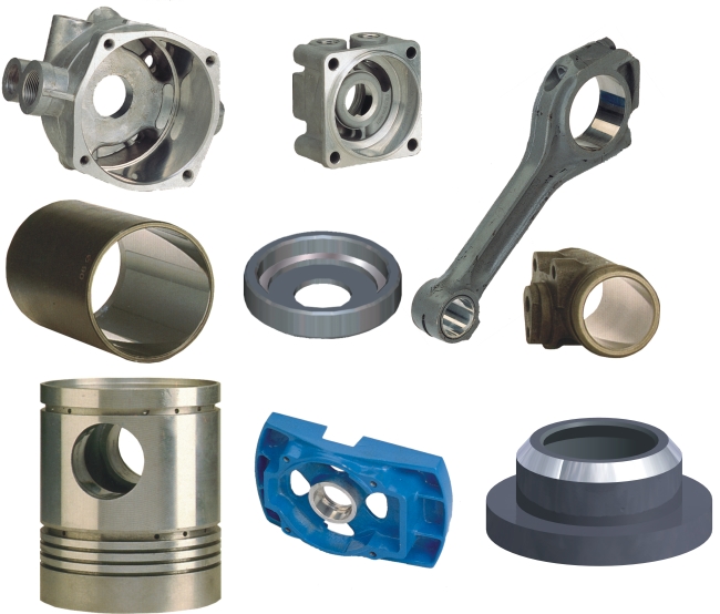 |
| Ezerek Parlatma Uygulama Örnek Resimleri |
Ezerek Parlatma Teknolojisinin Avantajları:
- Rz< 1µm ve altında çok düzgün yüzeyler elde edilebilir.
- Bu yöntemle istenilen ölçü kolay ve hızlı yakalanır.
- İşlem tek geçişte biter. işlem süresi, diğer yöntemlere oranla dakikalar yerine saniyelerle ölçülür.
- Ezme işlemi yüzeyi parlatırken, aynı zamanda sertleştirir. İşlem gören yüzeyin daha dayanıklı ve parlak hale gelmesini sağlar.
- Talaş, talaş tozu ve artıkları bırakmaz, gürültü çıkarmaz, çevreye zarar vermez.
- Takımlar tüm Universal ve CNC makinelere bağlanıp kullanılabilir .
- Takımlar oldukça dayanıklıdır. Aşınmadan kaynaklanan ölçü değişiklikleri olmadan uzun süre kullanılabilir.
Hazırlayan: Yamaç Aksan
Kaynaklar:
Aksan Teknik Mühendislik 2012 Kataloğu
1. Ezerek parlatma hangi malzemelerde uygulanabilir?
Çelik, alüminyum, bakır, paslanmaz çelik ve titanyum gibi çoğu metalde uygulanabilir.
2. Ezerek parlatma yüzey sertliğini nasıl etkiler?
Bu işlem, yüzeye baskı uygulayarak sertliğini artırır. Böylece daha dayanıklı ve estetik bir yüzey
elde edilir.
3. Ezerek Parlatma Takımının çap ayarı nasıl yapılır?
Takımın gövdesindeki ayar mekanizması adım adım döndürülerek hassas çap ayarı yapılır. Her bir
çizgi 2,5 mikron, tam bir tur 0,05 mm ayar sağlar. Ancak, ezilen malzemenin bir kısmı elastik
olarak esnediği için, aslında ayar daha hassas hale gelir.
4. Ezme payı nedir ve neden önemlidir?
Ezme payı, yüzeyde bırakılan ekstra malzeme kalınlığıdır. Bu pay, yüzeyin ezilerek pürüzsüz hale
gelmesini sağlar. İş parçasının boyutları ve malzeme türüne göre değişiklik gösterir.
5. Ezme payı fazla veya yetersiz olduğunda ne gibi sorunlar yaşanır?
Fazla ezme payı, gereksiz enerji tüketimine ve yüzeyde karıncalanma gibi bozulmalara yol
açabilir. Yetersiz ezme payı ise yüzeyde dalgalanmalara neden olabilir.
6. Ezerek parlatmada ön işleme neden önem verilmeli?
Uygun bir ön işlem, kaliteli yüzey elde edilmesini sağlar. Tornalama veya raybalama gibi
işlemlerle hazırlanmış yüzeyler idealdir. Yüzeyde ezilebilecek kadar pürüz bulunması gerekir.
7. Ezme payı malzeme türüne göre değişir mi?
Evet, çelik veya paslanmaz çelik gibi sert malzemeler daha az ezme payı gerektirir. Yumuşak
metallerde daha fazla ezme payına ihtiyaç duyulabilir. Başlangıç olarak 0,02-0,03 mm ezme payı
idealdir.
8. Ezme payı malzeme çapına göre değişir mi?
Evet, çap büyüdükçe daha fazla ezme payı gerekebilir. Geniş çaplı parçalar, düzgün yüzey elde
etmek için daha yüksek ezme payına ihtiyaç duyar.
9. Ezerek parlatma işlemi için uygun et kalınlığı nedir?
Çapın en az %10’u kadar et kalınlığı önerilir. Örneğin, 20 mm çapında bir parça için minimum 2
mm et kalınlığı gereklidir. İnce et kalınlıkları deformasyon riskini artırır.
10. Ezerek parlatma işlemi için uygun malzeme sertliği nedir?
Genellikle, malzeme sertliğinin 40 HRC’nin altında olması önerilir. Isıl işlem görmemiş
malzemeler genellikle bu işleme daha uygundur.
11. Kör delik takımları neden daha az çap ayarı yapabiliyor?
Ezerek parlatma takımlarında çap ayarı, konik milin ileri geri hareketiyle yapılır. Takım çapı
büyüdükçe, konik milin uç kısmının deliğin dibine çarpma riski artar. Kademeli deliklerde ise konik
mil kademeye girebilir. Bu gibi durumlarda, kör delik takımlarında daha fazla çap ayarı yapılabilir.
12. Kendi Çeker takımlar nedir, nerelerde kullanılır?
Takımın kendi çeker özelliği, bilyelerdeki helis açısı sayesinde elde edilir. Bu özellik, manuel
tezgahlarda kullanım kolaylığı sağlar. Sütunlu matkapta veya universal tornada yalnızca devir
vermek yeterlidir; takım, iş parçasının içinde otomatik olarak ilerler. Kılavuz çekmeye benzer bir
kullanım sağlar.
13. Kendi Çeker takımlar CNC tezgahta kullanılabilir mi?
Evet, kendi çeker takımlar CNC tezgahlarda da kullanılabilir. Bunun için tezgahın ilerleme hızının,
takımın kendi çekme hızından yüksek olması gerekir. İlerleme hızı düşük olursa takım tam ezme
sağlayamaz, ancak bu durum takıma zarar vermez. Uygun ilerleme hızı, birkaç deneme ile kolayca
bulunarak takım CNC’de rahatça kullanılabilir.
14. Ezerek Parlatma takımının hangi parçaları aşınır?
Ezerek Parlatma takımlarında en çok aşınan parçalar bilyelerdir. Bilyeler, yüzeyle sürekli temas
halinde oldukları için zamanla aşınabilir. Ayrıca, konik mil de zamanla aşınır. Ancak, bu işlem
kesici olmadığı için, takımın ömrü konvansiyonel kesici takımlara göre çok daha uzundur.
15. Bilyeler tek tek değiştirilebilir mi?
Hayır, bilyeler set olarak değiştirilir. Birkaç set bilye değişiminden sonra ise konik milin
değiştirilmesi gerekebilir.
16. Ezerek parlatma takımlarını nasıl satın alabilirim?
Sipariş veya bilgi için web sitemizden bize ulaşabilirsiniz.
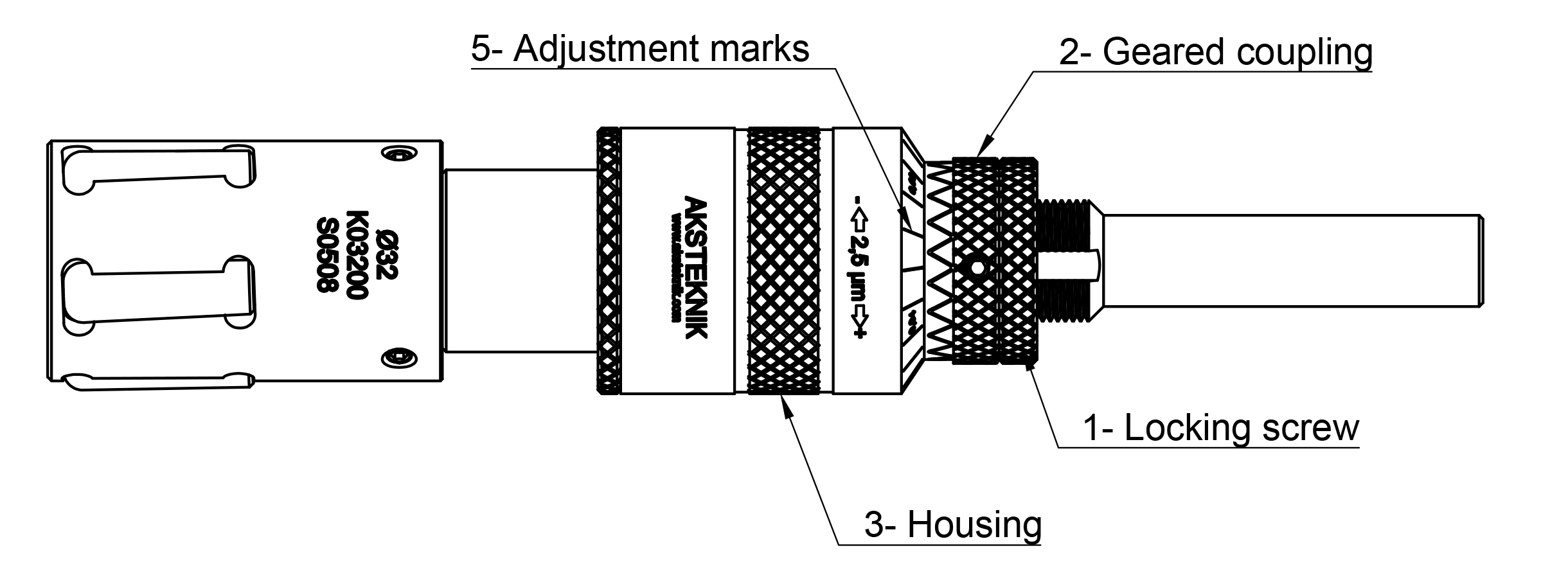
ÇAP AYARI
Kilitleme vidasını gevşetin.
Sabitleme dişlisini geri çekin.
Takım çapını küçülterek (gövdeyi sağa döndürerek), takımın iş parçasına rahatça sığmasını sağlayın.
Takım iş parçasına rahatça girdikten sonra, çapı büyütmek için gövdeyi sola doğru döndürün. Bu işleme, bilyeler iş parçasının yüzeyine temas edene kadar devam edin. (Takım çapı = iş parçası çapı) Temas sağlandıktan sonra takımı iş parçasından geri çekerek çıkarın.
Takım çapı ile iş parçası çapının aynı olduğundan emin olduktan sonra; gövde üzerindeki kademeli ayar işaretlerini (.0001″/.0025mm) kullanarak, takımın çapını deliğin içinde bıraktığınız ezme payı kadar daha büyültün.
Son ayar, bir iş parçası üzerinde parlatma işlemi yapılarak ve hem boyutları hem de yüzey kalitesi kontrol edilerek gerçekleştirilir. Aynı iş parçasını iki defadan fazla parlatmamak tavsiye edilir. Her ayardan sonra kilitleme somununun sıkı olduğundan emin olun.
DEVİR & İLERLEME
| Çap Aralığı (mm) | İlerleme (min) (mm/rev) | İlerleme (max) (mm/rev) | Devir (RPM) |
|---|---|---|---|
| 4mm – 9mm | 0.13 mm/rev | 0.31 mm/rev | 1500 to 3000 |
| 9mm – 16mm | 0.31 mm/rev | 0.51 mm/rev | 1000 to 2000 |
| 16mm – 22mm | 0.48 mm/rev | 0.69 mm/rev | 600 to 1200 |
| 22mm – 32mm | 0.56 mm/rev | 1.25 mm/rev | 600 to 1200 |
| 32mm – 44mm | 1.22 mm/rev | 1.80 mm/rev | 300 to 600 |
| 44mm – 57mm | 1.45 mm/rev | 2.67 mm/rev | 200 to 400 |
| 57mm – 70mm | 1.91 mm/rev | 3.15 mm/rev | 170 to 340 |
| 70mm – 95mm | 1.37 mm/rev | 2.95 mm/rev | 170 to 340 |
| 95mm – 108mm | 1.98 mm/rev | 3.07 mm/rev | 100 to 200 |
EZME MİKTARI
| İş parçası çap aralığı (mm) | Çapta ezme payı. (mm) | |
Sünek malzemeler (40Rc’nin altında): tavlanmış çelik, paslanmaz çelik, alüminyum, pirinç ve bronz. | 4mm-12mm | 0.01 – 0.02 |
| 12mm-25mm | 0.02 – 0.04 | |
| 25mm-50mm | 0.02 – 0.05 | |
| 50mm-165mm | 0.04 – 0.08 | |
| Düşük süneklilikteki malzemeler (41Rc’nin üzerinde): gri dökme demir, küresel dökme demir, ısıl işlem görmüş çelik, magnezyum alaşımları ve sert bakır alaşımları. | 4mm-12mm | 0.010 – 0.02 |
| 12mm-25mm | 0.02 – 0.03 | |
| 25mm-50mm | 0.03 – 0.04 | |
| 50mm-165mm | 0.04 – 0.05 |
Yağlama
- İşlem sırasında, hem takımı hem de iş parçasını iyice temizlemek ve yıkamak için yeterli miktarda temiz yağlayıcının sürekli bir akışını sağlayın.
- Çoğu metal için standart, hafif ve düşük viskoziteli bir yağlayıcı yağ önerilir. Ayrıca, %8 veya daha yüksek ideal konsantrasyona sahip suyla karışabilir soğutucular da kullanılabilir. Alüminyum veya magnezyum alaşımlarıyla çalışırken, düşük viskoziteli, rafine edilmiş bir parafin bazlı yağ en uygun seçenektir.
- Soğutma sistemi olmayan matkap tezgahlarında, doğru yağlama sağlamak için temiz yağlayıcıyı doğrudan takıma veya iş parçasına bol miktarda uygulayın.
Hizalama
- Takım ve iş parçasının doğru hizalanması, optimum performans için kritik öneme sahiptir. 0,10 mm’lik hafif bir hizalama hatası, takımın veya yüzeyin performansını önemli ölçüde etkilemez. Ancak, daha büyük hizalama hataları, mandren ucunda yorulma ve potansiyel arızalara yol açabilecek bükülme gerilmelerine neden olabilir. Doğru hizalama, özellikle takım dönerken daha da önem kazanır.
- Takım işlem sırasında, herhangi bir eksenel hareketi önlemek için sıkıca monte edilmelidir. Bu durum, dikey pozisyonda çalışan daha büyük ve daha ağır takımlar için özellikle önem taşır. Çok milli otomatik makinelerde, talaş birikimini azaltmak amacıyla takımın üst pozisyona yerleştirilmesi tavsiye edilir. Takım yatay düzlemde çalışırken, takımın deliğe doğru düzgün bir şekilde hizalanmasını sağlamak için iş parçasına geniş bir pah açısı verilmelidir.
Önemli Notlar
- Ezerek parlatma takımları her zaman saat yönünde çalıştırılmalıdır.
- Aynı parçayı iki defadan fazla parlatmaktan kaçının, çünkü tekrarlanan kullanım malzemenin iş sertleşmesine neden olabilir. Bu durum pullanmaya ve yanlış takım ayarlarına yol açabilir.
- Daha sert malzemelerle çalışırken, en iyi sonuçları elde etmek için devir sayısını önerilen değerlerin altına düşürmek gerekebilir.
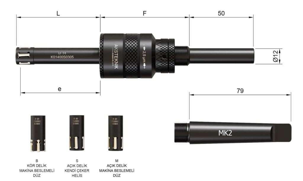
| Çap Ø | Ayar Aralığı | Ölçüler | Bilyeler | |||||||
|---|---|---|---|---|---|---|---|---|---|---|
| Açık Delik | Kör Delik | Ezme Boyu | L | F | Açık Delik | Kör Delik | ||||
| M | S | B | e | Kod | Bilye Adedi | Kod | Bilye Adedi | |||
| 9 | -0.10 +0.30 | -0.10 +0.40 | -0.00 +0.15 | 60 | 66 | 70 | BM02 | 4 | BB02 | 4 |
| 9.5 | -0.10 +0.30 | -0.10 +0.40 | -0.00 +0.15 | 60 | 66 | 70 | BM02 | 4 | BB02 | 4 |
| 10 | -0.10 +0.30 | -0.10 +0.40 | -0.00 +0.15 | 60 | 66 | 70 | BM03 | 4 | BB03 | 4 |
| 10.5 | -0.10 +0.30 | -0.10 +0.40 | -0.00 +0.15 | 60 | 66 | 70 | BM03 | 4 | BB03 | 4 |
| 11 | -0.10 +0.30 | -0.10 +0.40 | -0.00 +0.15 | 60 | 66 | 70 | BM03 | 5 | BB03 | 5 |
| 11.5 | -0.10 +0.30 | -0.10 +0.40 | -0.00 +0.15 | 60 | 66 | 70 | BM03 | 5 | BB03 | 5 |
| 12 | -0.10 +0.30 | -0.10 +0.40 | -0.00 +0.15 | 60 | 66 | 70 | BM03 | 5 | BB03 | 5 |
| 12.5 | -0.10 +0.30 | -0.10 +0.40 | -0.00 +0.15 | 60 | 66 | 70 | BM03 | 5 | BB03 | 5 |
| 13 | -0.10 +0.30 | -0.10 +0.40 | -0.00 +0.15 | 60 | 66 | 70 | BM03 | 5 | BB03 | 3 |
| 13.5 | -0.10 +0.30 | -0.10 +0.40 | -0.00 +0.15 | 60 | 66 | 70 | BM03 | 5 | BB03 | 5 |
| 14 | -0.10 +0.30 | -0.10 +0.40 | -0.00 +0.15 | 60 | 66 | 70 | BM03 | 5 | BB03 | 5 |
| 14.5 | -0.10 +0.30 | -0.10 +0.40 | -0.00 +0.15 | 60 | 66 | 70 | BM03 | 5 | BB03 | 5 |
| 15 | -0.10 +0.30 | -0.10 +0.40 | -0.00 +0.15 | 60 | 66 | 70 | BM03 | 5 | BB03 | 5 |
| 15.5 | -0.10 +0.30 | -0.10 +0.40 | -0.00 +0.15 | 60 | 66 | 70 | BM03 | 5 | BB03 | 5 |
| 16 | -0.10 +0.30 | -0.10 +0.40 | -0.00 +0.15 | 60 | 66 | 70 | BM03 | 5 | BB03 | 5 |
| 16.5 | -0.10 +0.30 | -0.10 +0.40 | -0.00 +0.15 | 60 | 66 | 70 | BM03 | 5 | BB03 | 5 |
| 17 | -0.10 +0.30 | -0.10 +0.40 | -0.00 +0.15 | 60 | 66 | 70 | BM05 | 5 | BB05 | 5 |
| 17.5 | -0.10 +0.30 | -0.10 +0.40 | -0.00 +0.15 | 60 | 66 | 70 | BM05 | 5 | BB05 | 5 |
| 18 | -0.10 +0.30 | -0.10 +0.40 | -0.00 +0.15 | 60 | 66 | 70 | BM05 | 5 | BB05 | 5 |
| 18.5 | -0.10 +0.30 | -0.10 +0.40 | -0.00 +0.15 | 60 | 66 | 70 | BM05 | 5 | BB05 | 5 |
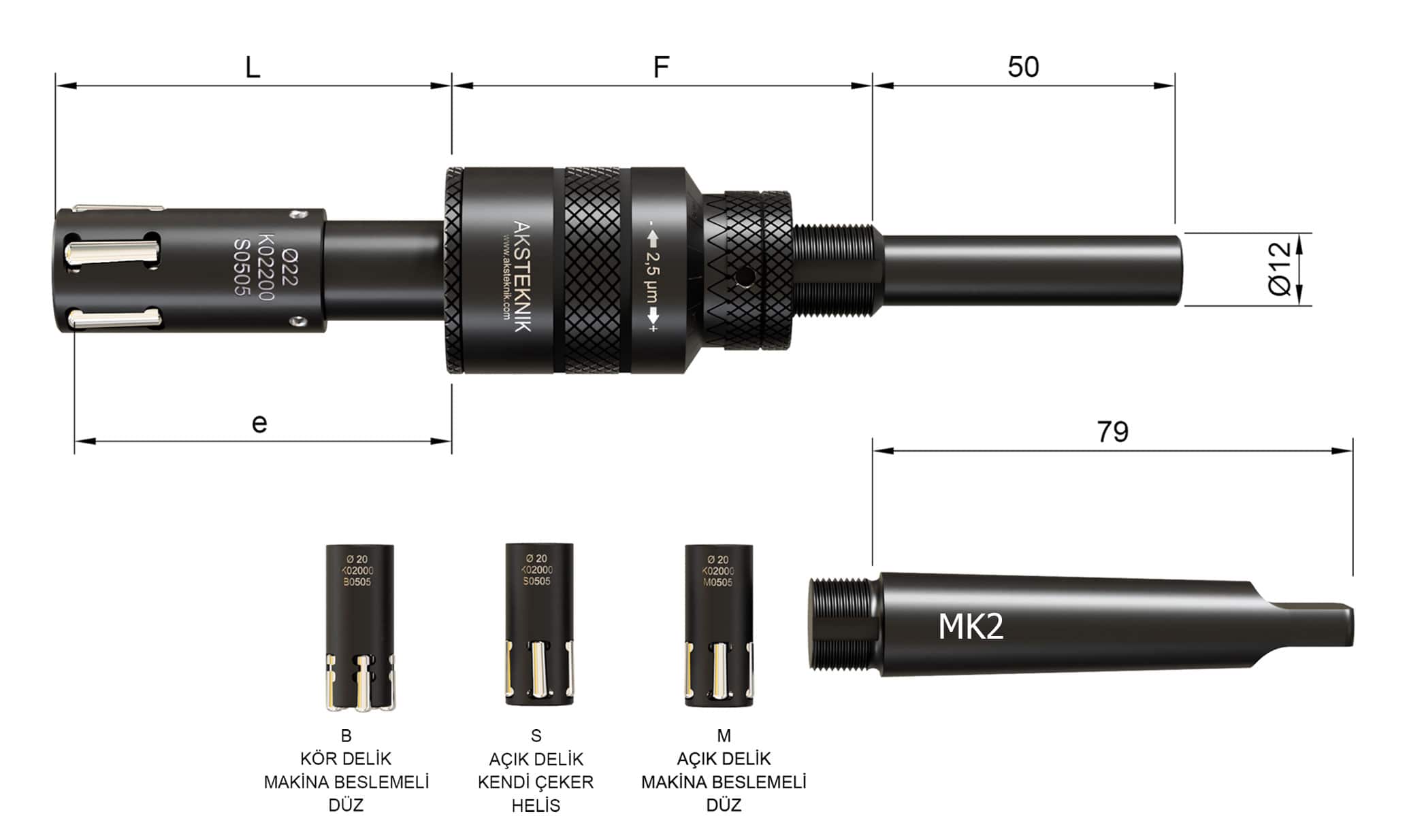
| Çap Ø | Ayar Aralığı | Ölçüler | Bilyeler | |||||||
|---|---|---|---|---|---|---|---|---|---|---|
| Açık Delik | Kör Delik | Ezme Boyu | L | F | Açık Delik | Kör Delik | ||||
| M | S | B | e | Kod | Bilye Adedi | Kod | Bilye Adedi | |||
| 19 | -0.10 +0.40 | -0.10 +0.40 | -0.00 +0.25 | 60 | 66 | 70 | BM05 | 5 | BB05 | 5 |
| 19.5 | -0.10 +0.40 | -0.10 +0.40 | -0.00 +0.25 | 60 | 66 | 70 | BM05 | 5 | BB05 | 5 |
| 20 | -0.10 +0.40 | -0.10 +0.40 | -0.00 +0.25 | 60 | 66 | 70 | BM05 | 5 | BB05 | 5 |
| 20.5 | -0.10 +0.40 | -0.10 +0.40 | -0.00 +0.25 | 60 | 66 | 70 | BM05 | 5 | BB05 | 5 |
| 21 | -0.10 +0.40 | -0.10 +0.40 | -0.00 +0.25 | 60 | 66 | 70 | BM05 | 5 | BB05 | 5 |
| 21.5 | -0.10 +0.40 | -0.10 +0.40 | -0.00 +0.25 | 60 | 66 | 70 | BM05 | 5 | BB05 | 5 |
| 22 | -0.10 +0.40 | -0.10 +0.40 | -0.00 +0.25 | 60 | 66 | 70 | BM05 | 5 | BB05 | 5 |
| 22.5 | -0.10 +0.40 | -0.10 +0.40 | -0.00 +0.25 | 60 | 66 | 70 | BM05 | 5 | BB05 | 5 |
| 23 | -0.10 +0.40 | -0.10 +0.40 | -0.00 +0.25 | 60 | 66 | 70 | BM05 | 5 | BB05 | 3 |
| 23.5 | -0.10 +0.40 | -0.10 +0.40 | -0.00 +0.25 | 60 | 66 | 70 | BM05 | 5 | BB05 | 5 |
| 24 | -0.10 +0.40 | -0.10 +0.40 | -0.00 +0.25 | 60 | 66 | 70 | BM05 | 5 | BB05 | 5 |
| 24.5 | -0.10 +0.40 | -0.10 +0.40 | -0.00 +0.25 | 60 | 66 | 70 | BM05 | 5 | BB05 | 5 |
| 25 | -0.10 +0.40 | -0.10 +0.40 | -0.00 +0.25 | 60 | 66 | 70 | BM05 | 5 | BB05 | 5 |
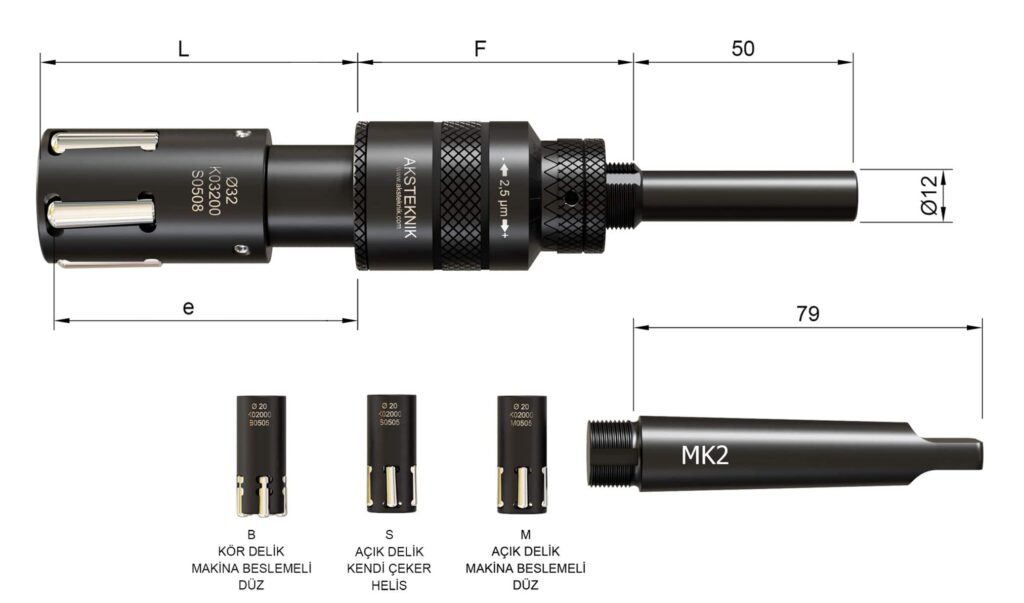
| Çap Ø | Ayar Aralığı | Ölçüler | Bilyeler | |||||||
|---|---|---|---|---|---|---|---|---|---|---|
| Açık Delik | Kör Delik | Ezme Boyu | L | F | Açık Delik | Kör Delik | ||||
| M | S | B | e | Kod | Bilye Adedi | Kod | Bilye Adedi | |||
| 25 | -0.10 +0.40 | -0.10 +0.40 | -0.00 +0.25 | 65 | 72 | 67 | BM05 | 5 | BB05 | 5 |
| 25.5 | -0.10 +0.40 | -0.10 +0.40 | -0.00 +0.25 | 65 | 72 | 67 | BM05 | 5 | BB05 | 5 |
| 26 | -0.10 +0.40 | -0.10 +0.40 | -0.00 +0.25 | 65 | 72 | 67 | BM05 | 5 | BB05 | 5 |
| 26.5 | -0.10 +0.40 | -0.10 +0.40 | -0.00 +0.25 | 65 | 72 | 67 | BM05 | 5 | BB05 | 5 |
| 27 | -0.10 +0.40 | -0.10 +0.40 | -0.00 +0.25 | 65 | 72 | 67 | BM05 | 5 | BB05 | 5 |
| 27.5 | -0.10 +0.40 | -0.10 +0.40 | -0.00 +0.25 | 65 | 72 | 67 | BM05 | 5 | BB05 | 5 |
| 28 | -0.10 +0.40 | -0.10 +0.40 | -0.00 +0.25 | 65 | 72 | 67 | BM05 | 5 | BB05 | 5 |
| 28.5 | -0.10 +0.40 | -0.10 +0.40 | -0.00 +0.25 | 65 | 72 | 67 | BM08 | 5 | BB08 | 5 |
| 29 | -0.10 +0.40 | -0.10 +0.40 | -0.00 +0.25 | 65 | 72 | 67 | BM08 | 5 | BB08 | 5 |
| 29.5 | -0.10 +0.40 | -0.10 +0.40 | -0.00 +0.25 | 65 | 72 | 67 | BM08 | 5 | BB08 | 5 |
| 30 | -0.10 +0.40 | -0.10 +0.40 | -0.00 +0.25 | 65 | 72 | 67 | BM08 | 5 | BB08 | 5 |
| 30.5 | -0.10 +0.40 | -0.10 +0.40 | -0.00 +0.25 | 65 | 72 | 67 | BM08 | 5 | BB08 | 5 |
| 31 | -0.10 +0.40 | -0.10 +0.40 | -0.00 +0.25 | 65 | 72 | 67 | BM08 | 5 | BB08 | 5 |
| 31.5 | -0.10 +0.40 | -0.10 +0.40 | -0.00 +0.25 | 65 | 72 | 67 | BM08 | 5 | BB08 | 5 |
| 32 | -0.10 +0.40 | -0.10 +0.40 | -0.00 +0.25 | 65 | 72 | 67 | BM08 | 5 | BB08 | 5 |
| 32.5 | -0.10 +0.40 | -0.10 +0.40 | -0.00 +0.25 | 65 | 72 | 67 | BM08 | 5 | BB08 | 5 |
| 33 | -0.10 +0.40 | -0.10 +0.40 | -0.00 +0.25 | 65 | 72 | 67 | BM08 | 5 | BB08 | 5 |
| 33.5 | -0.10 +0.40 | -0.10 +0.40 | -0.00 +0.25 | 65 | 72 | 67 | BM08 | 5 | BB08 | 5 |
| 34 | -0.10 +0.40 | -0.10 +0.40 | -0.00 +0.25 | 65 | 72 | 67 | BM08 | 5 | BB08 | 5 |
| 34.5 | -0.10 +0.40 | -0.10 +0.40 | -0.00 +0.25 | 65 | 72 | 67 | BM08 | 5 | BB08 | 5 |
| 35 | -0.10 +0.40 | -0.10 +0.40 | -0.00 +0.25 | 65 | 72 | 67 | BM08 | 5 | BB08 | 5 |
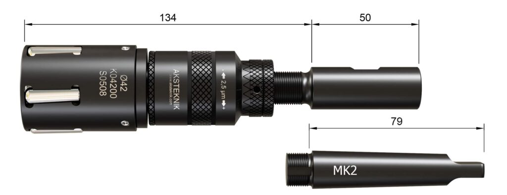
| Çap Ø | Ayar Arralığı | Ezme Boyu | Bilyeler | |||||||
|---|---|---|---|---|---|---|---|---|---|---|
| Açık Delik | Kör Delik | Açık Delik | Kör Delik | |||||||
| M | S | B | Kod | Bilye Adedi | Kod | Bilye Adedi | ||||
| 35.5 | -0.10 +0.40 | -0.10 +0.40 | -0.00 +0.25 | ∞ SINIRSIZ | BM08 | 5 | BB08 | 5 | ||
| 36 | -0.10 +0.40 | -0.10 +0.40 | -0.00 +0.25 | BM08 | 5 | BB08 | 5 | |||
| 36.5 | -0.10 +0.40 | -0.10 +0.40 | -0.00 +0.25 | BM08 | 5 | BB08 | 5 | |||
| 37 | -0.10 +0.40 | -0.10 +0.40 | -0.00 +0.25 | BM08 | 5 | BB08 | 5 | |||
| 37.5 | -0.10 +0.40 | -0.10 +0.40 | -0.00 +0.25 | BM08 | 5 | BB08 | 5 | |||
| 38 | -0.10 +0.40 | -0.10 +0.40 | -0.00 +0.25 | BM08 | 5 | BB08 | 5 | |||
| 38.5 | -0.10 +0.40 | -0.10 +0.40 | -0.00 +0.25 | BM08 | 5 | BB08 | 5 | |||
| 39 | -0.10 +0.40 | -0.10 +0.40 | -0.00 +0.25 | BM08 | 5 | BB08 | 5 | |||
| 39.5 | -0.10 +0.40 | -0.10 +0.40 | -0.00 +0.25 | BM08 | 5 | BB08 | 5 | |||
| 40 | -0.10 +0.40 | -0.10 +0.40 | -0.00 +0.25 | BM08 | 5 | BB08 | 5 | |||
| 40.5 | -0.10 +0.40 | -0.10 +0.40 | -0.00 +0.25 | BM08 | 5 | BB08 | 5 | |||
| 41 | -0.10 +0.40 | -0.10 +0.40 | -0.00 +0.25 | BM08 | 5 | BB08 | 5 | |||
| 41.5 | -0.10 +0.40 | -0.10 +0.40 | -0.00 +0.25 | BM08 | 5 | BB08 | 5 | |||
| 42 | -0.10 +0.40 | -0.10 +0.40 | -0.00 +0.25 | BM08 | 5 | BB08 | 5 | |||
| 42.5 | -0.10 +0.40 | -0.10 +0.40 | -0.00 +0.25 | BM08 | 5 | BB08 | 5 | |||
| 43 | -0.10 +0.40 | -0.10 +0.40 | -0.00 +0.25 | BM08 | 5 | BB08 | 5 | |||
| 43.5 | -0.10 +0.40 | -0.10 +0.40 | -0.00 +0.25 | BM08 | 5 | BB08 | 5 | |||
| 44 | -0.10 +0.40 | -0.10 +0.40 | -0.00 +0.25 | BM08 | 5 | BB08 | 5 | |||
| 44.5 | -0.10 +0.40 | -0.10 +0.40 | -0.00 +0.25 | BM08 | 5 | BB08 | 5 | |||
| 45 | -0.10 +0.40 | -0.10 +0.40 | -0.00 +0.25 | BM08 | 5 | BB08 | 5 | |||
| 45.5 | -0.10 +0.40 | -0.10 +0.40 | -0.00 +0.25 | BM05 | 5 | BB08 | 5 | |||
| 46 | -0.10 +0.40 | -0.10 +0.40 | -0.00 +0.25 | BM08 | 5 | BB08 | 5 | |||
| 46.5 | -0.10 +0.40 | -0.10 +0.40 | -0.00 +0.25 | BM08 | 5 | BB08 | 5 | |||
| 47 | -0.10 +0.40 | -0.10 +0.40 | -0.00 +0.25 | BM08 | 5 | BB08 | 5 | |||
| 47.5 | -0.10 +0.40 | -0.10 +0.40 | -0.00 +0.25 | BM08 | 5 | BB08 | 5 | |||
| 48 | -0.10 +0.40 | -0.10 +0.40 | -0.00 +0.25 | BM08 | 5 | BB08 | 5 | |||
| 48.5 | -0.10 +0.40 | -0.10 +0.40 | -0.00 +0.25 | BM08 | 5 | BB08 | 5 | |||
| 49 | -0.10 +0.40 | -0.10 +0.40 | -0.00 +0.25 | BM08 | 5 | BB08 | 5 | |||
| 49.5 | -0.10 +0.40 | -0.10 +0.40 | -0.00 +0.25 | BM08 | 5 | BB08 | 5 | |||
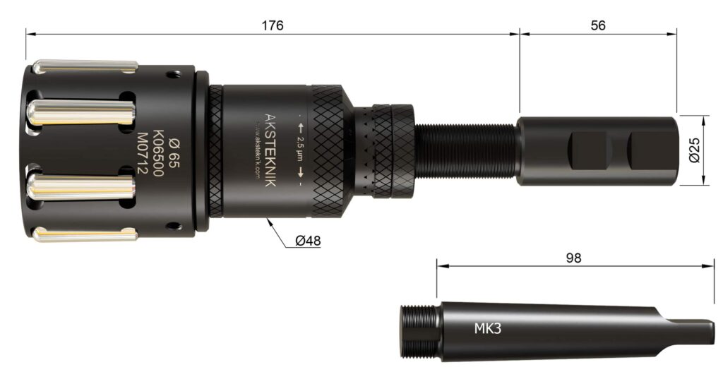
| Çap Ø | Ayar Arralığı | Ezme Boyu | Bilyeler | |||||||
|---|---|---|---|---|---|---|---|---|---|---|
| Açık Delik | Kör Delik | Açık Delik | Kör Delik | |||||||
| M | S | B | Kod | Bilye Adedi | Kod | Bilye Adedi | ||||
| 50 | -0.10 +0.80 | -0.10 +0.90 | -0.00 +0.25 | ∞ SINIRSIZ | BM12 | 5 | BB12 | 5 | ||
| 51 | -0.10 +0.80 | -0.10 +0.90 | -0.00 +0.25 | BM12 | 5 | BB12 | 5 | |||
| 52 | -0.10 +0.80 | -0.10 +0.90 | -0.00 +0.25 | BM12 | 5 | BB12 | 5 | |||
| 53 | -0.10 +0.80 | -0.10 +0.90 | -0.00 +0.25 | BM12 | 7 | BB12 | 7 | |||
| 54 | -0.10 +0.80 | -0.10 +0.90 | -0.00 +0.25 | BM12 | 7 | BB12 | 7 | |||
| 55 | -0.10 +0.80 | -0.10 +0.90 | -0.00 +0.25 | BM12 | 7 | BB12 | 7 | |||
| 56 | -0.10 +0.80 | -0.10 +0.90 | -0.00 +0.25 | BM12 | 7 | BB12 | 7 | |||
| 57 | -0.10 +0.80 | -0.10 +0.90 | -0.00 +0.25 | BM12 | 7 | BB12 | 7 | |||
| 58 | -0.10 +0.80 | -0.10 +0.90 | -0.00 +0.25 | BM12 | 7 | BB12 | 7 | |||
| 59 | -0.10 +0.80 | -0.10 +0.90 | -0.00 +0.25 | BM12 | 7 | BB12 | 7 | |||
| 60 | -0.10 +0.80 | -0.10 +0.90 | -0.00 +0.25 | BM12 | 7 | BB12 | 7 | |||
| 61 | -0.10 +0.80 | -0.10 +0.90 | -0.00 +0.25 | BM12 | 7 | BB12 | 7 | |||
| 62 | -0.10 +0.80 | -0.10 +0.90 | -0.00 +0.25 | BM12 | 7 | BB12 | 7 | |||
| 63 | -0.10 +0.80 | -0.10 +0.90 | -0.00 +0.25 | BM12 | 7 | BB12 | 7 | |||
| 64 | -0.10 +0.80 | -0.10 +0.90 | -0.00 +0.25 | BM12 | 7 | BB12 | 7 | |||
| 65 | -0.10 +0.80 | -0.10 +0.90 | -0.00 +0.25 | BM12 | 7 | BB12 | 7 | |||
| 66 | -0.10 +0.80 | -0.10 +0.90 | -0.00 +0.25 | BM12 | 7 | BB12 | 7 | |||
| 67 | -0.10 +0.80 | -0.10 +0.90 | -0.00 +0.25 | BM12 | 7 | BB12 | 7 | |||
| 68 | -0.10 +0.80 | -0.10 +0.90 | -0.00 +0.25 | BM12 | 7 | BB12 | 7 | |||
| 69 | -0.10 +0.80 | -0.10 +0.90 | -0.00 +0.25 | BM12 | 7 | BB12 | 7 | |||
| 70 | -0.10 +0.80 | -0.10 +0.90 | -0.00 +0.25 | BM12 | 7 | BB12 | 7 | |||
| 71 | -0.10 +0.80 | -0.10 +0.90 | -0.00 +0.25 | BM12 | 9 | BB12 | 9 | |||
| 72 | -0.10 +0.80 | -0.10 +0.90 | -0.00 +0.25 | BM12 | 9 | BB12 | 9 | |||
| 73 | -0.10 +0.80 | -0.10 +0.90 | -0.00 +0.25 | BM12 | 9 | BB12 | 9 | |||
| 74 | -0.10 +0.80 | -0.10 +0.90 | -0.00 +0.25 | BM12 | 9 | BB12 | 9 | |||
| 75 | -0.10 +0.80 | -0.10 +0.90 | -0.00 +0.25 | BM12 | 9 | BB12 | 9 | |||
| 76 | -0.10 +0.80 | -0.10 +0.90 | -0.00 +0.25 | BM12 | 9 | BB12 | 9 | |||
| 77 | -0.10 +0.80 | -0.10 +0.90 | -0.00 +0.25 | BM12 | 9 | BB12 | 9 | |||
| 78 | -0.10 +0.80 | -0.10 +0.90 | -0.00 +0.25 | BM12 | 9 | BB12 | 9 | |||
| 79 | -0.10 +0.80 | -0.10 +0.90 | -0.00 +0.25 | BM12 | 9 | BB12 | 9 | |||
| 80 | -0.10 +0.80 | -0.10 +0.90 | -0.00 +0.25 | BM12 | 9 | BB12 | 9 | |||
| 81 | -0.10 +0.80 | -0.10 +0.90 | -0.00 +0.25 | BM12 | 9 | BB12 | 9 | |||
| 82 | -0.10 +0.80 | -0.10 +0.90 | -0.00 +0.25 | BM12 | 9 | BB12 | 9 | |||
| 83 | -0.10 +0.80 | -0.10 +0.90 | -0.00 +0.25 | BM12 | 9 | BB12 | 9 | |||
| 84 | -0.10 +0.80 | -0.10 +0.90 | -0.00 +0.25 | BM12 | 9 | BB12 | 9 | |||
| 85 | -0.10 +0.80 | -0.10 +0.90 | -0.00 +0.25 | BM12 | 9 | BB12 | 9 | |||
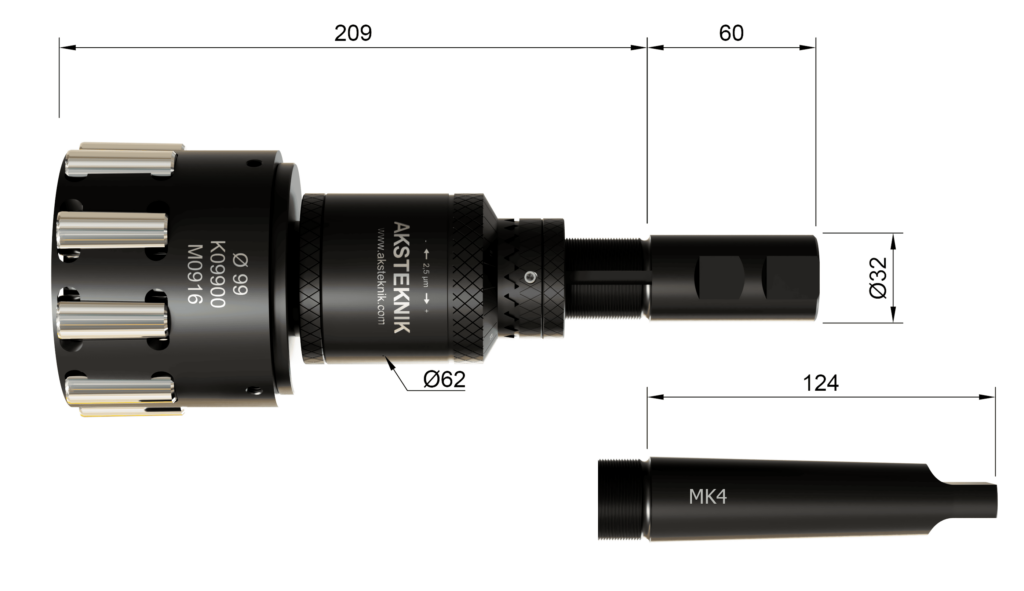
| Çap Ø | Ayar Arralığı | Ezme Boyu | Bilyeler | |||||||
|---|---|---|---|---|---|---|---|---|---|---|
| Açık Delik | Kör Delik | Açık Delik | Kör Delik | |||||||
| M | S | B | Kod | Bilye Adedi | Kod | Bilye Adedi | ||||
| 86-91 | -0.10 +0.80 | -0.10 +0.90 | -0.00 +0.25 | SINIRSIZ∞ | BM16 | 9 | BB16 | 9 | ||
| 92-99 | -0.10 +0.80 | -0.10 +0.90 | -0.00 +0.25 | BM16 | 9 | BB16 | 9 | |||
| 100-109 | -0.10 +0.80 | -0.10 +0.90 | -0.00 +0.25 | BM16 | 11 | BB16 | 11 | |||
| 110-121 | -0.10 +0.80 | -0.10 +0.90 | -0.00 +0.25 | BM20 | 9 | BB20 | 9 | |||
| 122-135 | -0.10 +0.80 | -0.10 +0.90 | -0.00 +0.25 | BM20 | 11 | BB20 | 11 | |||
| 136-150 | -0.10 +0.80 | -0.10 +0.90 | -0.00 +0.25 | BM20 | 11 | BB20 | 11 | |||
| 151-160 | -0.10 +0.80 | -0.10 +0.90 | -0.00 +0.25 | BM20 | 13 | BB20 | 13 | |||


